Megger Tester Voltage: Which Range to Use and When
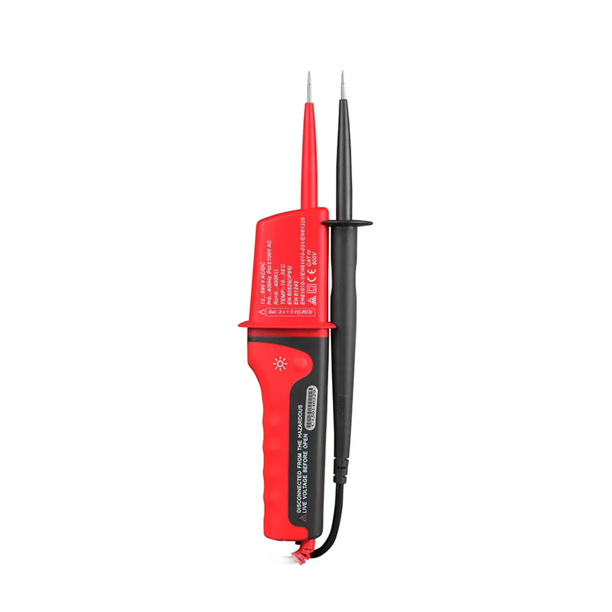
Megger tester voltage is the DC voltage an insulation resistance tester applies to stress cable insulation — not the voltage of the circuit itself. Under BS 7671 Table 64 you test SELV and PELV circuits at 250 V DC, standard circuits up to 500 V (that is normal 230 V and 400 V work) at 500 V DC, and circuits above 500 V at 1000 V DC. Pick the range from the circuit's nominal voltage, and remember: a megger checks insulation, it never proves a circuit dead.
What "megger tester voltage" actually means
An insulation resistance tester deliberately applies a known DC voltage across insulation and measures how little current leaks through, reporting the result in megohms (MΩ). The applied voltage is the "megger tester voltage" — a stress test level you select, entirely separate from the 230 V the circuit runs at. Healthy insulation resists the applied voltage; damaged, damp or nail-pierced insulation lets current leak and the reading collapses.
If the concept feels backwards in college — pushing voltage into a cable to check that nothing conducts — that is the point of the test: you are proving the insulation holds at a voltage tougher than everyday service. One naming note: Megger is a manufacturer's brand that has become trade slang, the way "Hoover" stands in for vacuum cleaner. The instrument is an insulation resistance (IR) tester, and everything below applies whichever brand is on the case.
The three test voltages and when each applies
BS 7671 sets the test voltages in Table 64, and the pattern is easy to memorise because it follows the circuit's nominal voltage:
| Circuit nominal voltage | Test voltage (DC) | Minimum insulation resistance |
|---|---|---|
| SELV and PELV circuits | 250 V | 0.5 MΩ |
| Up to and including 500 V (standard 230 V / 400 V circuits) | 500 V | 1.0 MΩ |
| Above 500 V | 1000 V | 1.0 MΩ |
- 250 V DC is for extra-low-voltage circuits — SELV and PELV, such as bell transformers and some lighting systems — where a 500 V test could punch through insulation that is perfectly adequate for 12 V or 24 V service.
- 500 V DC is the everyday setting for domestic and commercial work: 230 V single-phase and 400 V three-phase circuits all test at 500 V.
- 1000 V DC only comes out for circuits with a nominal voltage above 500 V, which for most UK electricians means occasional industrial work.
Those minimums are pass thresholds, not comfort levels. New wiring typically reads in the hundreds of megohms or over-range; a result limping along at 1–2 MΩ passes on paper but is telling you to investigate.
The 250 V two-stage test with equipment connected
The most common exam-day slip is forgetting Regulation 643.3.3. Where connected equipment would skew the result or be damaged by the test — think dimmers, USB sockets, smart controls — you test in two stages: first the wiring alone at the Table 64 voltage (500 V DC for standard circuits), then, after the equipment is connected, a gentler test at 250 V DC between the live conductors joined together and the protective conductor. That second reading must be at least 1 MΩ.
The two-stage rule exists because electronics and surge protective devices can both distort readings and die at 500 V. Disconnecting or testing around them first, then confirming at 250 V, protects the kit and still proves the finished installation.
Why a megger never proves dead
An IR tester is a source of voltage, not a detector of it. Before any insulation test you must isolate the circuit and prove it dead with a two-pole voltage detector and a proving unit — the prove-test-prove routine we walk through in our voltage tester with proving unit guide. Meggering a live circuit risks the instrument, the installation and you.
Keep the two jobs in separate mental boxes: the two-pole tester answers "is this circuit dead?", the megger answers "is this dead circuit's insulation healthy?". You need both answers, in that order, every time.
Running an insulation test without surprises
- Isolate and prove dead with a GS38-compliant two-pole detector, proving the detector before and after.
- Disconnect or protect sensitive equipment — unplug loads, note SPDs and electronics, and plan the two-stage test where they cannot be removed.
- Select the test voltage from Table 64 — 500 V DC for a standard circuit, 250 V DC for SELV/PELV.
- Test between live conductors, then live conductors to earth, recording each reading against the circuit on the schedule.
- Let the circuit discharge — cables hold charge after the test; keep the leads connected a moment so the instrument bleeds it off before you touch anything.
- Investigate low readings before energising: damp accessories, pierced cables and shared neutrals are the usual suspects.
Where the UT15C fits alongside a megger
An IR tester is a significant purchase, and if you are an apprentice assembling a first kit on a tight budget it is usually the college's or your employer's instrument you will use for a while. The tool that must be your own from day one is the safe isolation tester that comes before every megger test. The ATUTEN UT15C covers that half of the job for £64.04 including VAT: a GS38-compliant two-pole detector with shrouded fused probes, 12 V–690 V AC/DC indication that works even without batteries, a continuity buzzer for dead testing, and an IP65 body that shrugs off site conditions — with a 12-month UK warranty behind it.
Between the two instruments you have the complete pre-energisation story: prove dead with the two-pole tester, then prove the insulation with the megger at the right Table 64 voltage. If you are still choosing that first detector, our GS38 voltage tester guide covers what assessors expect it to look like.
Frequently Asked Questions
What megger tester voltage should I use on a 230 V domestic circuit?
500 V DC. BS 7671 Table 64 puts all circuits up to and including 500 V nominal — which covers 230 V single-phase and 400 V three-phase — on a 500 V DC test with a minimum acceptable reading of 1.0 MΩ.
When do I test at 250 V DC instead?
Two cases: SELV and PELV circuits, where 250 V DC with a 0.5 MΩ minimum applies; and the second stage of Regulation 643.3.3, where equipment that could be damaged has been connected and you confirm at 250 V DC between joined live conductors and earth, expecting at least 1 MΩ.
Can I use a megger to check a circuit is dead?
No. An insulation resistance tester applies voltage rather than detecting it. Prove the circuit dead first with a GS38-compliant two-pole voltage detector and a proving unit, then run the insulation test.
Why is my insulation reading low but still above 1 MΩ?
Readings between 1 MΩ and 2 MΩ pass the Table 64 minimum but are low for healthy wiring, which normally reads far higher. Moisture in accessories, ageing rubber insulation or a pierced cable are common causes — investigate before energising rather than certifying a borderline result.
Ready to try ATUTEN UK?
Shop Now — £64.04